

Staad.Pro- Design and analysis of a G+5 residential building
INTRODUCTION
There are many classical methods to solve design problems, and with time new software’s also coming into play. Here in this project work based on the software named Staad.Pro has been used.
From model generation, analysis and design to visualization and result verification, STAAD Pro is the professional’s choice for steel, concrete, timber, aluminum and cold-formed steel design of low and high-rise buildings, culverts, petrochemical plants, tunnels, bridges, piles and much more.
Advanced structural analysis may examine dynamic response, stability and non-linear behavior. Few standard problems also have been solved to show how “STAAD. Pro” can be used in different cases. These typical problems have been solved using basic concept of loading, analysis, condition as per IS code 456:2000. These basic techniques may be found useful for further analysis of problems.
DESIGN OF STRUCTURE ELEMENT
The aim of design is to achievement of an acceptable probability that structure being designed will perform satisfactorily during their intended life.
The design of any structure is categorized into the following two main types:
- Functional design
- Structural design
STAGE IN STRUCTURE DESIGN
The process of structure design involves the following stages:
- Structure planning
- Acton of forces and computation of loads
- Method design
- Member design
- Detailing, drawing and preparation of schedules
BEAM
There are three types of reinforced concrete beams –
- Single reinforced beam
- Double reinforced beams
- Flanged beams
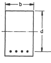
Single Reinforced Beams
In singly reinforced simply supported beams steel bars are placed near the bottom of the beam where they are effective in resisting the tensile bending stress.
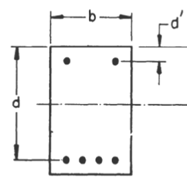
Double Reinforced Beams
It is reinforced under compression tension regions. The necessities of steel of the compression region arise due to two reasons. When the depth of the beam is restricted, the strength availability singly reinforced beam is inadequate.
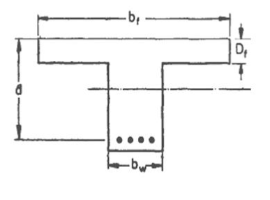
Flanged beams
There are two types of flanged beam.
1. T-beam
2. L-beam
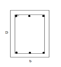
COLUMN
A column may be defined as an element used primarily to support axial compressive loads and with a height of a least three times its lateral dimension. The strength of the column depends upon the strength of materials, shape, and size of cross-section, length, and degree of proportional and dedicational restrains at its ends.
SLAB
Slabs are most widely used structural elements forming floor and roof of building. Slab support mainly transverse load and transfer them to supports by bending actions more or one directions. On the basis of spanning direction: It is two type one way slabs and two way slab.
One-way slab
When the slab is supported on two opposite side parallel edges, it spans only in the directions perpendicular to the supporting edges. It bends in one direction and main steel is provided in the directions of the span. Such a slab is known as a one-way slab.
One way continuous slab
In the case of large halls, auditoriums, marriage halls, etc. the length is divided into equal bays by providing beams perpendicular to the length. The slab provided over such an area is called a one-way continuous slab.

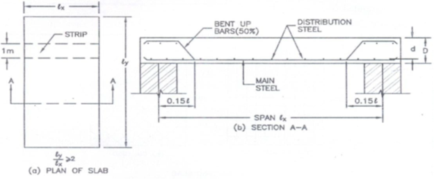
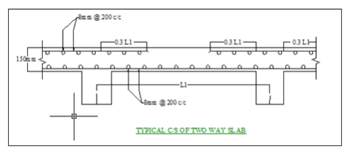
Two-way slab
When the supported on four edges and the load distribution is also on four edges of the panel. The reinforcement is provided on both sides. Such a slab is known as a two-way slab.
FOOTING
Foundations are structural elements that transfer loads from the building or individual column to the earth .If these loads are to be properly transmitted, foundations must be designed to prevent excessive settlement or rotation, to minimize differential settlement and to provide adequate safety against sliding and overturning.
There are three type of isolated column footing:
- Pad footing
- Stepped footing
- Slopped footing
INTRODUCTION to STAAD Pro –
It is one of the effective software which is used for the purpose of analysis and design of structure by the structural engineers. Our project is aimed to complete with the help of STAAD Pro. STADD Pro gives more precise and accurate results than manual techniques.
Features
- Analysis and design tool
- GUI based modeling
- Input file/Output file
- Results as per Indian & other standards
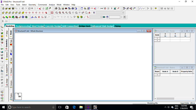
• Report generation In fig show s typical STAAD.Pro Window-
STEPS INVOLVED
The software follows the matrix stiffness principle in analyzing the structure. The steps for analyzing a structure using STAAD Pro are given below.
- Generation of nodes
- Modeling of the structure
- Restraints
- Assigning of the structure members
- Application of loads
- Run analysis
GENERATION OF NODE
The nodes are generated based on the dimensions of the building. The building is divided into an equal number of known grids. Then the grid spacing is given on the STAAD Pro window. The software automatically generates a grid with a specified window.
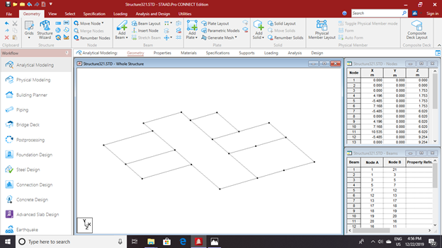
MODELLING OF THE STRUCTURE
After the nodes are created they are jointed with line elements in fig. Based on the dimension of the building the nodes are joined. Unwanted nodes could be deleted.

RESTRAINTS
After the structure has been modeled the restraints has to given.

ASSIGNING OF THE STRUCTURAL ELEMENTS
The software has the facility to assign the structural elements. The line elements have to be assigned as beam, column and plates and appropriate dimension are given.
Assigning of the beam
Beams are designed for flexure, shear, and torsion. If required the effect of the axial force may be taken into consideration. For all these forces, all active beam loadings are pre-scanned to identify the critical load cases at different sections of the beam.

Assigning of the column
Columns are designed for axial forces and biaxial moments per IS 456:2000. All major criteria for selecting longitudinal and transverse reinforcement as stipulated by IS:456 have been taken care of in the column design of STAAD.

Assigning of the plate
Plates are designed for floor loads. The plate thickness are provides 150mm.

3D MODEL VIEW
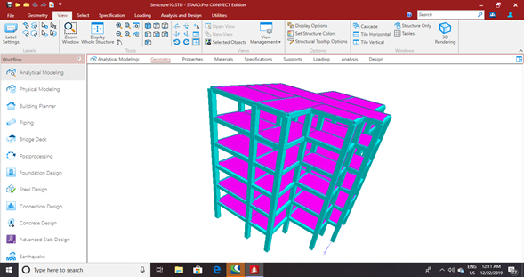
APPLICATION OF LOADS
There are the various loads acting on a structure.
- Self-weight
- Floor load
- Wind load
- Load combination
SELF WEIGHT
The self weight of the structure can be generated by STAAD.Pro itself with the self weight command in the load case column.

FLOOR LOAD
Floor load from the slab can also be generated by STAAD.Pro by specifying thickness and the load on the floor per sq m.
The live loads were generated in a similar manner as done in the earlier case for the dead load on each floor. This may be done from the member load button from the load case column.

WIND LOAD
The wind load values were generated by the software itself in accordance with IS 875. Under the defined load category, the definition of wind load was supplied. The wind intensities at various heights were calculated manually and feed to the software. Based on those values it generates the wind load on different floors.
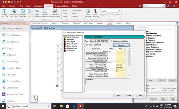
SEISMIC LOAD
The seismic load values were calculated as per IS1893-2002. STAAD Pro has a seismic load generator in accordance with the IS code mentioned.
The seismic load generator can be used to generate lateral load in the X and Z direction only. Y direction is the direction of gravity loads. This facility has not been developed for case where the Z axis is set to be the vertical direction using the “SET Z UP” command.
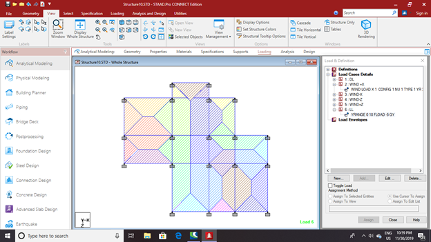
LOAD COMBINATION
The structure has been analyzed for load combination considering all previous loads in the proper ratio. In the first case of a combination of self-weight, dead load, live load, and wind load were taken into consideration. In the second combination case instead of wind load seismic load was taken into consideration
RUN ANALYSIS
When the last step, run analysis is executed it shows “Analysis complete”, which indicates the termination of the analysis process. Based on the analysis result, the building is designed in accordance with the provisions mentioned in the Indian Standard Codes.

DESIGN OF G+5 RCC FRAMED BUILDING USING STAAD.Pro
The structure was designed for concrete in accordance with IS code. The parameters such as clear cover, Fy, Fc, etc were specified. The window shown below is the input window for the design purpose. Then it has to be specified which member is to be designed as beam and which members are to be designed s columns.
Design Parameters
- CLEAR COVER FOR BEAM- 30mm
- CLEAR COVER FOR COLUMN- 50mm
- FC- 30000 N/mm2
- FY MAIN- 500000 N/mm2
- FY SEC- 500000 N/mm2
- MAX MAIN- 32mm
- MAX SEC- 20mm
- MIN MAIN- 16mm
- MIN SEC- 8mm
REINFORCEMENT DETAILING – BEAM, SLAB, COLUMN
Click Here


ANALYSIS AND DESIGN RESULTS
Beam Design
Some of the sample analysis and design result have been shown below for beam number 47 which is at the level of ground floor.
B E A M N O. 47 D E S I G N R E S U L T S
M25 Fe415 (Main) Fe415 (Sec.)
LENGTH: 4196.0 mm SIZE: 400.0 mm X 600.0 mm COVER: 25.0 mm
SUMMARY OF REINF. AREA (Sq.mm)
—————————————————————————-
SECTION 0.0 mm 1049.0 mm 2098.0 mm 3147.0 mm 4196.0 mm
—————————————————————————-
TOP 466.99 0.00 0.00 466.99 491.57
REINF. (Sq. mm) (Sq. mm) (Sq. mm) (Sq. mm) (Sq. mm)
BOTTOM 466.99 466.99 466.99 466.99 0.00
REINF. (Sq. mm) (Sq. mm) (Sq. mm) (Sq. mm) (Sq. mm)
—————————————————————————-
SUMMARY OF PROVIDED REINF. AREA
—————————————————————————-
SECTION 0.0 mm 1049.0 mm 2098.0 mm 3147.0 mm 4196.0 mm
—————————————————————————-
TOP 6-10н 6-10н6-10н6-10н 7-10н
REINF. 1 layer(s) 1 layer(s) 1 layer(s) 1 layer(s) 1 layer(s)
BOTTOM 6-10н 6-10н6-10н6-10н6-10н
REINF. 1 layer(s) 1 layer(s) 1 layer(s) 1 layer(s) 1 layer(s)
SHEAR 2 legged 8н 2 legged 8н 2 legged 8н 2 legged 8н 2 legged 8н
REINF. @ 225 mm c/c @ 225 mm c/c @ 225 mm c/c @ 225 mm c/c @ 225 mm c/c
—————————————————————————-
SHEAR DESIGN RESULTS AT DISTANCE d (EFFECTIVE DEPTH) FROM FACE OF THE SUPPORT
—————————————————————————–
SHEAR DESIGN RESULTS AT 820.0 mm AWAY FROM START SUPPORT
VY = 9.94 MX = 0.12 LD= 1
Provide 2 Legged 8н @ 225 mm c/c
SHEAR DESIGN RESULTS AT 820.0 mm AWAY FROM END SUPPORT
VY = -10.06 MX = 0.12 LD= 1 Provide 2 Legged 8н @ 225 mm c/c


COLUMN DESIGN
C O L U M N N O. 74 D E S I G N R E S U L T S
M25 Fe415 (Main) Fe415 (Sec.)
LENGTH: 3000.0 mm CROSS SECTION: 500.0 mm X 500.0 mm COVER: 40.0 mm
** GUIDING LOAD CASE: 1 END JOINT: 25 SHORT COLUMN
REQD. STEEL AREA : 291.60 Sq.mm.
REQD. CONCRETE AREA: 36450.42 Sq.mm.
MAIN REINFORCEMENT : Provide 8 – 12 dia. (0.36%, 904.78 Sq.mm.)
(Equally distributed)
TIE REINFORCEMENT : Provide 8 mm dia. rectangular ties @ 190 mm c/c
SECTION CAPACITY BASED ON REINFORCEMENT REQUIRED (KNS-MET)
———————————————————-
Puz : 2899.98 Muz1 : 106.31 Muy1 : 106.31
INTERACTION RATIO: 0.17 (as per Cl. 39.6, IS456:2000)
SECTION CAPACITY BASED ON REINFORCEMENT PROVIDED (KNS-MET)
———————————————————-
WORST LOAD CASE: 1
END JOINT: 25 Puz : 3083.93 Muz : 149.29 Muy : 149.29 IR: 0.12 _ STAAD SPACE — PAGE NO. 178

Material Used

Conclusion
STAAD PRO has the capability to calculate the reinforcement needed for any concrete section. The program contains a number of parameters which are designed as per IS: 456(2000). Beams are designed for flexure, shear and torsion.
Design for Flexure
Maximum sagging (creating tensile stress at the bottom face of the beam) and hogging (creating tensile stress at the top face) moments are calculated for all active load cases at each of the above-mentioned sections. Each of these sections are designed to resist both of these critical sagging and hogging moments. Where ever the rectangular section is inadequate as singly reinforced section, doubly reinforced section is tried.
Design for Shear
Shear reinforcement is calculated to resist both shear forces and torsional moments. Shear capacity calculation at different sections without the shear reinforcement is based on the actual tensile reinforcement provided by STAAD program. Two-legged stirrups are provided to take care of the balance shear forces acting on these sections.
Beam Design Output
The default design output of the beam contains flexural and shear reinforcement provided along the length of the beam.
Column Design
Columns are designed for axial forces and biaxial moments at the ends. All active load cases are tested to calculate reinforcement. The loading which yields maximum reinforcement is called the critical load. Column design is done for the square section. Square columns are designed with reinforcement distributed on each side equally for the sections under biaxial moments and with reinforcement distributed equally in two faces for sections under a uni-axial moment. All major criteria for selecting longitudinal and transverse reinforcement as stipulated by IS: 456 have been taken care of in the column design of STAAD.
Feel Free to Ask For .doc File
ask in comment section

Right Understanding
Right Understanding We all know that the Human Desire is to be in continuous happiness which is the need of I (self).…

Where We Are
Where We Are (Self-Evolution) We exist as human being. We want to live a fulfilling life. We have some desires and we…

Highway Construction
Highway Construction Embankment Construction Materials and General Requirements The materials used in embankments, subgrades, earthen, shoulders, and miscellaneous backfills shall be soil,…

Special Concretes
Special Concretes Concrete is most vital material in modern construction. In addition to normal concrete, other varieties in use are, high strength…

Marketing Practices
Marketing Practices Success in the world of business, no matter how you earn it, you have to rule on the marketplace. Although…

Risk Analysis
Risk Analysis The risk that remains after the implementation of controls is called the residual risk. All systems will have residual risk…


