

BRIDGE WORKSHOP
NORTH EASTERN RAILWAY GORAKHPUR

A SUMMER INTERNSHIP REPORT
Submitted by
SHIVANAND RAI
Batch- B1 Roll No-25
In partial fulfillment of of Industrial training for the award of the degree of
BACHELOR OF TECHNOLOGY
IN
2nd YEAR CIVIL ENGINEERING

RAJKIYA ENGINEERING COLLEGE MAINPURI
AGRA ROAD, NOUNER MAINPURI-205001
FROM 6th JUNE 2018 to 6th JULY 2018
CERTIFICATE
I hereby certify that I have completed the Four Week Training in the partial fulfillment of the requirements for the award of Bachelor of Technology Engineering. I did my training in BRIDGE WORKSHOP NORTH EASTERN RAILWAY GORAKHPUR from 06-06-2018 to 06-07-2018
The matter presented in this report has not been submitted by me for the award of any other degree elsewhere.
Signature of Student
CERTIFICATE
Certified that the industrial training project report “OPEN WEB GIRDER & M-50 GRADE CONCRETE” is the bonafide work of “SHIVANAND RAI, Roll No-1684000045” 2nd Year B.Tech. in CIVIL Engineering of Rajkiya Engineering College, Mainpuri of Abdul Kalam Technical University, Uttar Pradesh carried out under my super vision during 06-06-2018 to 06-07-2018
Place Signature of Supervisor
Date Name:
SUPERVISOR
Academic Designation
Department/Organization
ACKNOWLEDGEMENT
I would like to place on record my deep sense of gratitude to Er. VIKRAMA PRASAD for his generous guidance, help and useful suggestions.
I express my sincere gratitude to Er. KAMLESH PRASAD (SENIOR SECTION ENGINEER) for his stimulating guidance, and continuous encouragement.
I also wish to extend my thanks to Er. K GOPALAN and other workers for guiding and providing the knowledge regarding machinery and processes.
I am extremely thankful to my faculty Er. SAKET RUSIA, REC Mainpuri and training placement cell REC mainpuri for valuable suggestion and encouragement.
Signature of Student
ABSTRACT
Since the inception of Indian Railways in 1853, the Railway Engineers has a history of more than 150 years of construction and maintenance of railway bridges. During the long journey, they had achieved several heights and continuing to excellence. Recently Indian Railways has either constructed several world-class bridges or they are in the process of construction. A technical review of the design and construction of recent bridges (viz. Bogibeel, Chenab, and New Jubilee Bridges) through light on the recent technological advancements attained by the Indian Railways in the field of bridge engineering.
The joints of Riveted Steel Truss Railway Bridge consist of gusset plates which lose their rigidity due to repeated passages of train loads; therefore the loss of rotational rigidity is to be taken into account in analysis of Bridge. This joint flexibility tends to alter the vibration characteristics of the Bridge system and each component of the bridge responds dynamically to the rapidly varying loads and thus the time history obtained is a function of load variation and dynamics of the structure, which consequently affects fatigue life of the bridge components. In past, effect of semirigid joints has been studied in case of building frames.
So here the knowledge of semirigid joints on building frame has been extended to Steel Truss Railway Bridge. This present article tries to study the influence of joint flexibility on the fatigue life of 76.2 m Truss bridge due to moving load at different speeds. The joint rotational stiffness is reduced by 5%, 10%, 25% and 50%. The result of preliminary studies conducted on Steel Truss Bridge is presented. It is prime facia that up to 50% reduction in rotational Stiffness of the joints does not affect the stability of the bridge.
INTRODUCTION
TRUSS BRIDGE
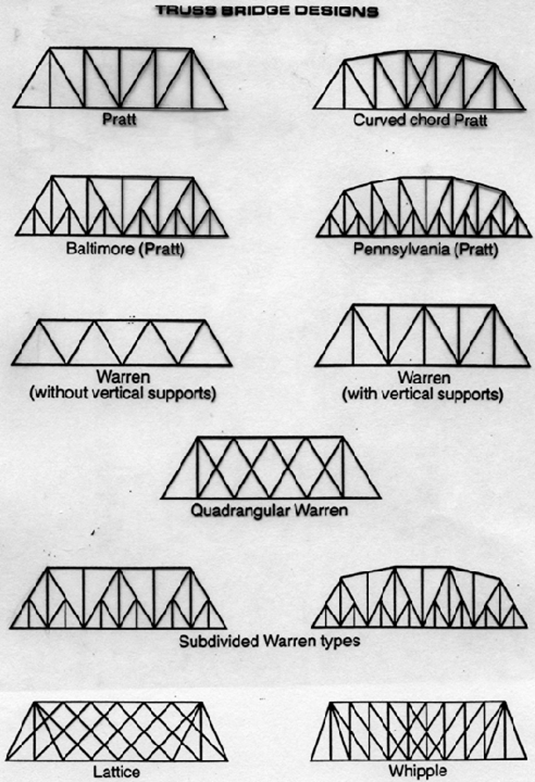
A truss bridge is a bridge whose load-bearing superstructure is composed of a truss, a structure of connected elements usually forming triangular units. The connected elements (typically straight) may be stressed from tension, compression, or sometimes both in response to dynamic loads. Truss bridges are one of the oldest types of modern bridges. The basic types of truss bridges shown in this article have simple designs which could be easily analyzed by 19th and early 20th-century engineers. A truss bridge is economical to construct because it uses materials efficiently.
The first metal truss bridges were constructed of wrought iron, but high-grade steel eventually replaced iron as a building material (Steel is stronger than wrought iron but nearly indistinguishable in appearance). Prior to 1885 bridge builder relied on wrought iron between 1885 and 1895, a boom in the united state steel industry led to the construction of a mixture of wrought iron and steel structures. By the turn of the century steel had replaced wrought iron for bridge building.
TYPES OF TRUSSES BRIDGE
WARREN GIRDER
INTRODUCTION
A girder is a support beam used in construction. It is the main horizontal support of a structure which supports smaller beams. Girders often have a beam cross composed of two load-bearing flanges separated by a stabilizing web, but may also have a box shape, Z shape and other forms. A girder is commonly used to build bridges.
In traditional timber framing a girder is called a girt.
Small steel girders are rolled into shape. Larger girders (1 m/3 feet deep or more) are made as plate girders, welded or bolted together from separate pieces of steel plate.
The Warren type girder replaces the solid web with an open latticework between the flanges. This truss arrangement combines strength with economy of materials and can therefore be relatively light. Patented in 1848 by its designers James Warren and Willoughby Theobald Monzani, its structure consists of longitudinal members joined only by angled cross-members, forming alternately inverted equilateral triangle-shaped spaces along its length, ensuring that no individual strut, beam, or tie is subject to bending or torsional straining forces, but only to tension or compression. It is an improvement over the Neville truss which uses a spacing configuration of isosceles triangles.
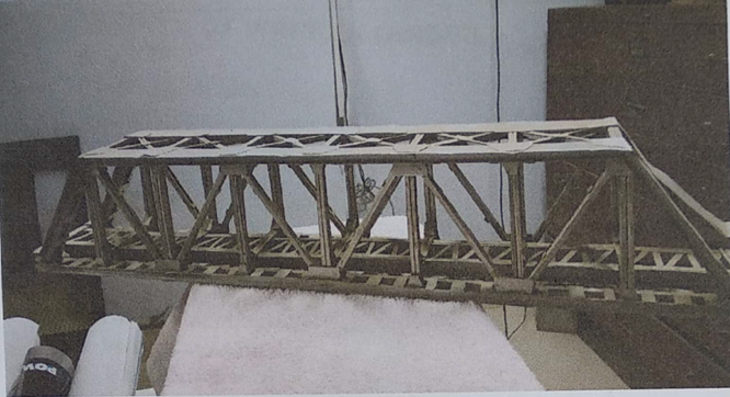
Warren girder can be stated as form of truss having parallel upper and lower chords, with connecting member which are inclined, forming a series of approximately equilateral triangles.
COMPONENTS OF WARREN GIRDER
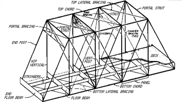
- PRIMARY MEMBERS:
- Bottom chord
- Top chord
- End racker/post
- Diagonals
- Vertical members
- Cross girders
- Stringers or Rail Bearers
- SECONDARY MEMBERS:
- Bottom Lateral Bracing
- Top Lateral Bracing
- Sway bracing
- Main Gussets
- Corner and End Gussets
- Bearings
FABRICATION:
The process of putting together properly shaped individual components to form the desired structure. It includes following procedure explained accordingly.
LAYOUT AND TEMPLATING
A: NEED FOR TEMPLATE:
There are two dimensions associated with templating in RDSO drawing for open web girder- Nominal length & Camber length as it is not possible to show all the intersection points of components, hence the drawing is laid in1:1 on shop floor called template shop, this process is called Templating. It’s needed for following reasons:
- Obtaining the missing dimensions and infringements at interaction points.
- To check for correctness of camber by verifying closing lengths.
- For obtaining the correct profiles of all gusset plates & preparing the master gusset plates for manufacturing of jigs for components at each panel joint.
B : TEMPLATE PROCESS
- LAYOUT: Layout is a drawing of complete structure on a full scale. Normally half span is drawn on a leveled smooth concrete floor. Nominal as well as Camber layout will be drawn on the floor. Drilling jigs for gusset plates for both side gussets and main gussets will be kept as per the nominal length and drilling jig for members i.e., web & flange will be kept as per camber length. Web drilling is done first & then flange drilling takes place.
- JIG & FIXTURE MAKING: Jigs are the devices used in the mass production of standard jobs for drilling holes without marking. A jig is a member with drilled holes of an individual component so that by placing this jig over or inside that component holes can be drilled. For guiding the drilling machine & to prevent oversizing of the holes of the jig, bushes are provided over it. The internal diameter of the bushes should be within the tolerance of 0.0mm to +0.1mm. When the bushes exceed the tolerance of -0.0mm to +0.4mm shall be rejected.

For every working jig, one master plate is manufactured. This master plate is just for the checking of the jigs. Tolerance for checking jigs from master plate is +0.0mm to -0.13mm.
C: CAMBER
- An upward concavity in the underside of a beam girder or a slight upward concavity in the straight arch.
- An arch whose intrados, though apparently straight, has a slight concave upward is called a cambered arch. Its length is slightly more than the nominal length.
- In order to ensure that the fabrication and erection of the main girder shall be such as to eliminate secondary stresses in the loaded span, the nominal length (i.e., The length which will give no camber) of the member shall be increased or decreased by the amount shown on the camber diagram by the purchaser.
- Camber is provided in an arch to prevent the bridge from sagging due to deflection during loading.


CUTTING OF PLATES
Inspection by PCO before cutting of raw material as per codal provisions required as per IS:2062 & IS:1862. First of all, the straightening of deformed sections of raw material is done. Cutting of plates to required size is done by using the following methods:

Pug cutting machine : Straight cutting machine that utillises a dissolved acetylene gas cylinder (red pipe) & oxygen cylinder (blue pipe). These gases are allowed to be mixed in the mixing chamber .The pressure & the amount of gases are preadjusted and the machine works automatically. The flame is obtained through containing 7 holes.
- 3 types of flames are obtained.
- Neutral- Used for proper cutting.
- Oxidizing-Contains more oxygen, unsuitable for cutting.
- Carbonizing-Contains more acetylene, unsuitable for cutting.
- After cutting It should be ensured that all edges are clean & reasonably square.
- CUTTING BY SUBMERGED CUTTING PROCESS

Under water CNC plasma cutting actually submerges the plate below 2” to 4” of water, so the torch tip & the entire arc are submerged. It prevents excessive noise & emission of smoke.
TACK ASSEMBLING THE COMPONENTS
The components i.e. the web with top and bottom flanges are joined through tack welding. After the steel plates are cut to obtain the required size & are straightened, they are temporarily joined through tack welding to form a composite member that will be placed in fixture & prepared for SAW process.
- Diameter of tacks = 50mm
- Distance between two consecutive tacks = 300mm
- Tack welding is to be done by AC welding transformer set as on following-
- Electrode- 4mm diameter, Type-A2,4212X
- CLASS- IRS-M-28/2002
- Current Type-AC
- Current = 180 amp (approx.)
- Arc Voltage = 80 volts(approx.)
SAW PROCESS

SAW stands for Submerged Arc Welding. After tack welding, the webs of two jobs are joined together through fillet welding of 6mm to 8mm by automatic SAW machine as on following approximates:
- 4 mm Copper coated wire CLASS-IRS-M-39/2001 (generally used for heavy works).
- Flux CLASS-IRSM-39/2001
- Current Type- DC
- Current = 500 to 600 amp
- Arc Voltage = 32 to 34 volts
- Wire feed speed (m/min) = 2.550 to 3.200
- Travel speed of SAW (m/min)=0.375 to 0.475
The flux used is steel rod coated with plus. This flux together with plus aids in burning and melting the metal.
SAW process has following advantages-
- Smooth weld.
- Deeper penetration of welding metal.
- Stronger & time-efficient.


INSPECTION OF WELDING
After SAW is done, inspection has to be performed & quality control measures have to be applied at local level. To ensure if the welding is done properly, 2 major tests are performed.
DPT
- DPT stands for Dye Penetration Test. It is done to check the presence of blow holes & crevices in the weld. It involves the use of 3 chemicals:
- Cleaner- Applied over the area, where SAW is done to clean it.
- Penetrant- Applied over the area to ensure the passage for the chemical to enter the weld.
- Developer- Developer is then sprayed which gives off bright pink spots at points where blowholes are located. These holes are then filled by manual welding.

MACRO ETCHING TEST
Macro etching test is performed to check the throat length & root fusion of weld metal at location of edge joints. It is also known as ACID TEST as it is conducted on smooth, clean surface by-
- Applying 2% nitric acid(HNO3).
- Cleaning with water.
- Cleaning with alcohol.
Thereafter the leg length, throat length and penetration are recorded.
DRILLING THE MEMBERS
The web plates are drilled first using web jig. The flange plates are then drilled using flange jig. The drilling machine used for drilling holes in thick plates is called a RADIAL DRILLING MACHINE. It is a fixed type of drilling machine as the bottom part of machine is fixed over the base, while the upper assembly can move with the help of track attached to upper part of the machine.
The hole drilled at the shop is 21.5mm holes & the hole drilled at site is 23.5mm hole. Only -0.0mm to +3.0mm tolerance is allowed.
Jigs should be lifted from the components after all holes are drilled to avoid difficulty in drill lifting over holes at later stages.
Also the rivet holes shall be 1.5mm greater than the diameter of the rivet bars used.
RIVETING OF COMPONENTS
RIVETING the joints through rivets is permanently fixing the joints. In it, single headed iron rivets are heated and fixed in position through pressure applied by a machine known as DOLLY. Then the rivet from the other end is made double headed through a machine known as RIVETING MACHINE.
- The clearance i.e. the difference in diameter between the rivets measured under head before being heated and the rivet hole shall not be less than 0.75mm.
- All rivets shall be properly heated to straw heat for the full length of the shank at a temperature of 750o-1000o C for 20 to 25 minutes. Then it is firmly backed & closed. The head of the rivet shall be heated more than the body. Sparking or burnt rivets shall be rejected.
- All loose & burnt rivets with cracks badly formed, eccentric or deficient heads shall be cut out & replaced.
- Steel rivets should conform to IS:1148 & rivet should be made conforming to IS:1929.
- Length of rivets=GRIP+1.5D+1mm extra to every 4mm GRIP.
- Compressed air pressure required at the hammer end is 6 to7 kg/sq.cm.
- The heating time of rivets is 20 to 25minutes.
- All the rivets should be tested by a responsible supervisor by using testing hammer weight 110 grams.
- When all the rivets of joints have been finally passed, they should be painted with one coat of ready mixed Zn-Cr primer to IS:104 followed by one coat of ready-mixed paint red oxide Zn-Cr primer to IS:2074.

USE OF HSFG BOLTING IN WARREN GIRDERS

Introduction- High Strength Friction Grip (HSFG) bolts are high strength structural bolts that have been tightened such as to induce tension in the bolt shank. Due to the tension in the bolt, the interface between the plies (steel members in a joint) cannot move relative to each other because of the friction resistance. The bolt acts differently than normal bolts.
FINAL INSPECTION OF THE MEMBERS
Final inspection of the members is done by RDSO. It includes-
- Inspection by M & C wing for welding quality & procedure.
- Inspection by structural wing for structural work.
- Before metalizing & painting all components of open web girder are to be offered for inspection by RDSO as per fabrication specification B1-2001 & welded bridge code IRS-2001.
- INSPECTION BY M & C WING
- Visual inspection
- Mechanical inspection
- Non-destructive test(DPT)
- Destructive test (MACRO ETCHING TEST)
- INSPECTION BY STRUCTURAL WING FOR WELDING QUALITY
- The overall length of the member.
- The distance of the center of bearings.
- Depth of girder.
- Diagonal length.
- Centre of intersection angles.
- Straightness of girder.
- Distance between inner to inner holes.
- Distance between outer to outer holes.
- Edge distance.
- Quality of rivets.
- Pitch of the holes.
- Checking of weld profile as DP.
- INSPECTION BY M & C WING
METALIZING & PAINTING
Metalizing & painting of components and stenciling of shipping marks followed as per metalizing & painting schedule IRS: B1-2001 Appendix-VII.
- Surface preparation for metalizing as per SA 2.5 grade by grit/sandblasting. This process removes rust & cleans the surface of rust, dirt, and chippings.


Then followed by Metalizing process by metal spraying through a machine that uses Aluminum wire of 4mm diameter. This Aluminum is 99.6% pure. The nominal thickness of this coating shall be 150 microns (checking by eclometer DFT).

Then etch primer conforming to the IS:5666 coat shall be applied on Aluminium coating.

One coat of Zn-Cr conforming to IS:104 of nominal thickness 25-30 microns shall be applied.

Followed by one coat of Aluminium paint conforming to IS:2339 of nominal thickness of 25-30 microns shall be applied.

Final Aluminium coating is applied on site.

Then shipping marks are stenciled and the parts is sent to the construction site for assembly.
MIX DESIGN OF M-50 GRADE CONCRETE
Nominal Mixes: Earlier, specifications for concrete are set the ratios of cement and fine coarse aggregates. This mixes of fixed cement & aggregate ratio makes sure sufficient strength in concrete and it is termed as nominal mixes.
The strength of the nominal concrete for a specified workability fluctuates significantly because of the difference of mix components. In this type of mix, all the ingredients are prearranged and their proportions are given. Nominal mix contains volumetric batching. It is mainly utilized for comparatively insignificant and simpler concrete works. Nominal mix concrete generally utilized for concrete of M-20 or lower.
Standard Mixes: The nominal mixes of fixed cement-aggregate ratio (by volume) differentiate greatly in strength and may lead to under or over-rich mixes. Due to this, the least compressive strength is contained in various specifications. These mixes are described as standard mixes.
As per IS 456-2000 standard, the concrete mixes are divided into several grades like M10, M15, M20, M25, M30, M35 and M40. Here M denotes the mix and number to the number to the stipulated 28 day cube strength of mix in N/mm2.
The mixes of grades M10, M15, M20 and M25 conform roughly to the mix proportions (1:3:6), (1:2:4), (1:1:5:3) and (1:1:2) correspondingly.
The mix design M-50 grade (Using Admixture –Sikament) provided here is for reference purpose only. Actual site conditions vary and thus this should be adjusted as per the location and other factors.
Parameters for mix design M50
Grade Designation = M-50
Type of cement = O.P.C-43 grade
Brand of cement = Vikram (Grasim)
Admixture = Sika [Sikament 170 (H)]
Fine Aggregate = Zone-II
Sp. Gravity
Cement = 3.15
Fine Aggregate = 2.61
Coarse Aggregate (20mm) = 2.65
Coarse Aggregate (10mm) = 2.66
Minimum Cement (As per contract) =400 kg / m3
Maximum water cement ratio (As per contract) = 0.45
Mix Calculation: –
1. Target Mean Strength = 50 + ( 5 X 1.65 ) = 58.25 Mpa
2. Selection of water-cement ratio:-
Assume water cement ratio = 0.35
3. Calculation of water: –
Approximate water content for 20mm max. Size of aggregate = 180 kg /m3 (As per Table No. 5 , IS : 10262 ). As plasticizer is proposed we can reduce water content by 20%.
Now water content = 180 X 0.8 = 144 kg /m3
4. Calculation of cement content: –
Water cement ratio = 0.35
Water content per cum of concrete = 144 kg
Cement content = 144/0.35 = 411.4 kg / m3
Say cement content = 412 kg / m3 (As per contract Minimum cement content 400 kg / m3 )
Hence O.K.
5. Calculation for C.A. & F.A.: [ Formula’s can be seen in earlier posts]-
Volume of concrete = 1 m3
Volume of cement = 412 / ( 3.15 X 1000 ) = 0.1308 m3
Volume of water = 144 / ( 1 X 1000 ) = 0.1440 m3
Volume of Admixture = 4.994 / (1.145 X 1000 ) = 0.0043 m3
Total weight of other materials except coarse aggregate = 0.1308 + 0.1440 +0.0043 = 0.2791 m3
Volume of coarse and fine aggregate = 1 – 0.2791 = 0.7209 m3
Volume of F.A. = 0.7209 X 0.33 = 0.2379 m3 (Assuming 33% by volume of total aggregate )
Volume of C.A. = 0.7209 – 0.2379 = 0.4830 m3
Therefore weight of F.A. = 0.2379 X 2.61 X 1000 = 620.919 kg/ m3
Say weight of F.A. = 621 kg/ m3
Therefore weight of C.A. = 0.4830 X 2.655 X 1000 = 1282.365 kg/ m3
Say weight of C.A. = 1284 kg/ m3
Considering 20 mm: 10mm = 0.55: 0.45
20mm = 706 kg
10mm = 578 kg
Hence Mix details per m3
Increasing cement, water, admixture by 2.5% for this trial
Cement = 412 X 1.025 = 422 kg
Water = 144 X 1.025 = 147.6 kg
Fine aggregate = 621 kg
Coarse aggregate 20 mm = 706 kg
Coarse aggregate 10 mm = 578 kg
Admixture = 1.2 % by weight of cement = 5.064 kg.
Water: cement: F.A.: C.A. = 0.35: 1: 1.472: 3.043
Observation: –
A. Mix was cohesive and homogeneous.
B. Slump = 120 mm
C. No. of cube cast = 9 Nos.
7 days average compressive strength = 52.07 MPa.
28 days average compressive strength = 62.52 MPa which is greater than 58.25MPa
Hence the mix accepted.

WATER BOUND MACADAM BITUMINOUS ROAD
Roads provide access to the outside world or the store around the corner. Roads take farm produce to market and children to school. Roads are the conduit of life’s activities.

NATIONAL HIGHWAY 2
NATIONAL HIGHWAY 2 A SUMMER TRAINING REPORT Submitted by Abhijeet Katiyar 1684000002 In partial fulfillment of industrial training for the award of the degree of BACHELOR OF TECHNOLOGY IN CIVIL ENGINEERING Rajkiya Engineering College, Mainpuri RECM NH84, Road Nauner, Bhongoan – Mainpuri – Shikohabad Road, Mainpuri Uttar Pradesh 205001 June – July 2019 AKNOWLEDGEMENT I…

CONSTRUCTION OF OFFICE BUILDING
CONSTRUCTION OF OFFICE BUILDING A SUMMER TRAINING REPORT Submitted by SHRISHTI TRIPATHI 1684000047 In partial fulfilment of industrial training for the award of the degree of BACHELOR OF TECHNOLOGY IN CIVIL ENGINEERING Rajkiya Engineering College, Mainpuri NH84 Road Nauner, Mainpuri – Shikohabad Road Mainpuri, Uttar Pradesh 205001 JULY 2019 ABSTRACT The internship report in broad-spectrum…

Staad.Pro- Design and analysis of a G+5 residential building
Staad.Pro- Design and analysis of a G+5 residential building INTRODUCTION There are many classical methods to solve design problems, and with time new software’s also coming into play. Here in this project work based on the software named Staad.Pro has been used. From model generation, analysis and design to visualization and result verification, STAAD Pro…
Continue Reading Staad.Pro- Design and analysis of a G+5 residential building

NATIONAL HIGHWAY 730
NATIONAL HIGHWAY 730 A SUMMER TRAINING REPORT Submitted by Abhijeet Katiyar 1684000002 In partial fulfillment of industrial training for the award of the degree of BACHELOR OF TECHNOLOGY IN CIVIL ENGINEERING Rajkiya Engineering College, Mainpuri RECM NH84 Road Nauner, Bhongoan – Mainpuri – Shikohabad Road, Mainpuri Uttar Pradesh 205001 July 2018 ACKNOWLEDGEMENT I would like…


